Click the links below to go directly to each example
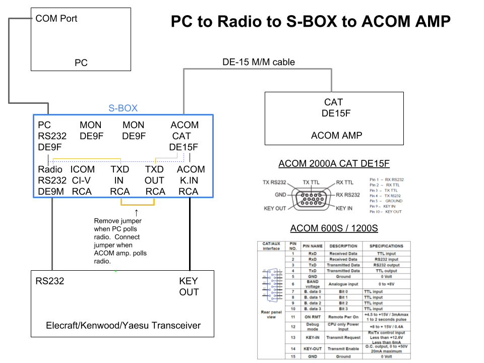
With a standard serial cable connected between the S-BOX Radio RS-232 connector and a supported Elecraft, Kenwood or Yaesu transceiver, the ACOM amplifier can monitor the transceiver frequency and automatically change bands as required. PTT from the transceiver may also be routed to the ACOM KEY IN line over the same cable, as shown. A standard DE-15 M/M cable connects the 15-pin CAT connector on the S-BOX to the 15-pin CAT connector on the new ACOM RCU.
The TXD line from the amplifier, used for polling, is not connected when a logging program is in use, because only one device can poll the radio at a time. However, with no PC connected, a simple RCA jumper cable or external switch can be used to connect the polling signals from the amplifier to the transceiver.
Click to view PDF.
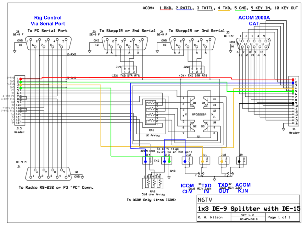
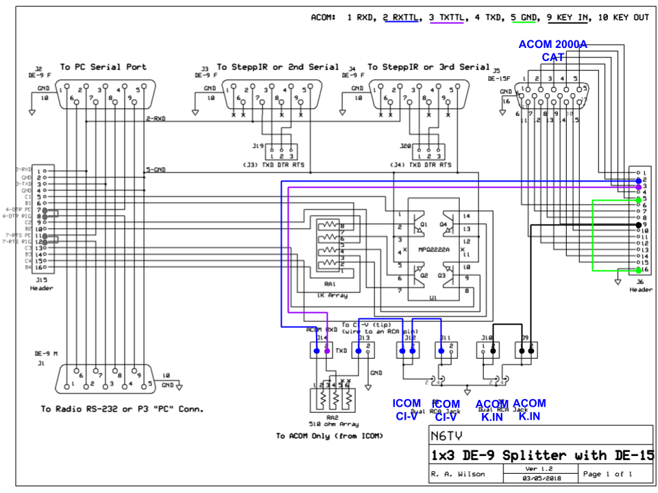
With jumper wires connected to pins 1 and 5 of the 15-pin header as shown by the red (RXD) and green (GND) lines below, the RS-232 signals between the PC and transceiver can be monitored by the ACOM amplifier.
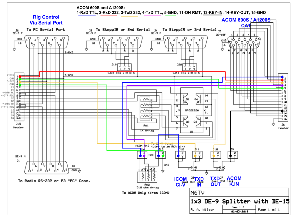
The ACOM 600S and A1200S use the same DE-15F connector, but different pins than the ACOM 2000A, so the jumper wires are connected to different pins on the header, as shown below. Cable connections are the same shown in the block diagram above.
Click to view PDF.
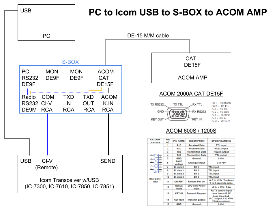
With a standard RCA-to-Stereo patch cable connected from the first RCA connector on the S-BOX labeled ICOM CI-V to the REMOTE (CI-V) connector on the transceiver, the ACOM amplifier can monitor the transceiver frequency to automatically change bands as required. KEY OUT (SEND) from the Icom transceiver may also be routed to the ACOM KEY IN line over the same cable. A DE-15 M/M cable connects the 15-pin CAT connector on the S-BOX to the 15-pin CAT connector on the new ACOM RCU.
Click to view PDF.
This S-BOX includes the CI-V to TTL conversion circuit documented in the ACOM 2000A manual, as indicated by the blue and gray lines in the schematic below.
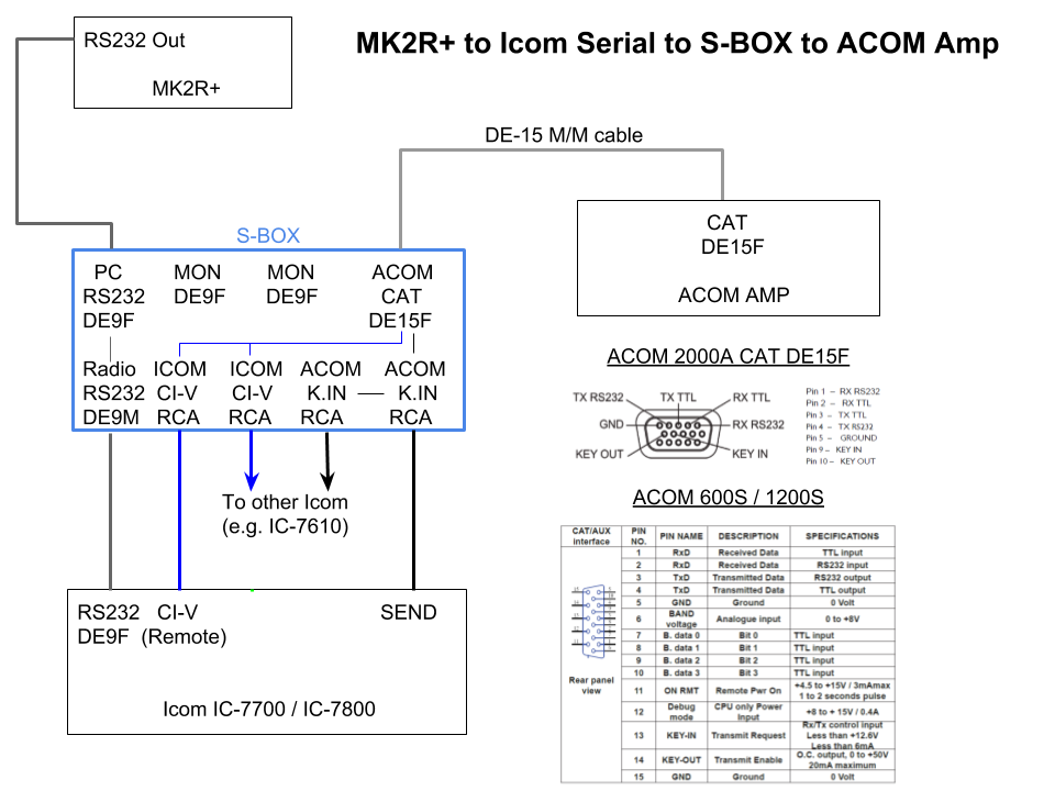
With jumper wires connected to the first two RCA connectors as shown by the blue lines below, an Icom transceiver can provide CI-V frequency data to an ACOM amplifier for automatic band changes. PTT from either transceiver may also be routed to the AMP over the same 15-pin M/M CAT cable.
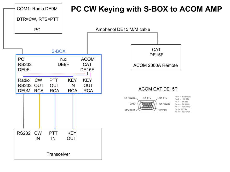
The internal keying circuits of the S-BOX make it easy to use a single serial port for both rig control via “CAT” and CW and PTT keying, even if your transceiver doesn't support this feature.
A single Amphenol® DE-15 M/M cable connects the RS-232 signals and KEY IN from the S-BOX to the 15-pin ACOM RCU CAT port. The ACOM amplifier will then track the frequency of the transceiver automatically as long as a logging program is running.
Click to view PDF.
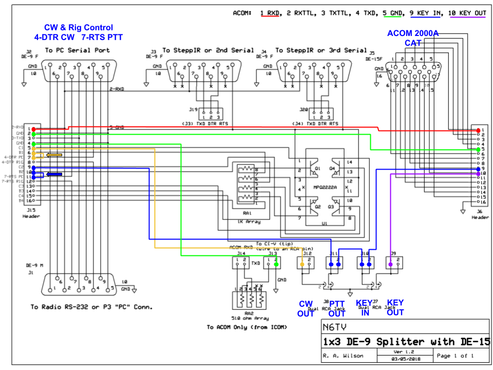
With the two shunt jumpers in the position shown below, all nine serial port pins are passed straight through from the PC serial port (J2, DE-9F, top) to the transceiver connector (J1, DE9-M, bottom):
However, if both shunt jumpers are moved up one position, as indicated by the yellow and blue arrows below, this disconnects RS-232 pin 4 (DTR) and pin 7 (RTS) from the transceiver, connecting them instead to the base (input) of two independent NPN keying transistors (labeled B1 and B2 on the header).
The collectors of these transistors (the output, C1 and C2) are then connected to the RCA connector headers to provide CW and PTT keying to the transceiver, as shown in the schematic below. The PTT output is also wired directly to the ACOM KEY IN line (pin 9), closing the amplifier's relay as soon as PTT is asserted by the logging program. Connecting the KEY OUT (relay) line of the transceiver to the RCA connector labeled KEY IN will hold the amplifier relay closed until the transceiver or logging program opens the line, whichever is later. This provides a safe and fast way to close the amplifier's relay in case the transceiver is late closing the RELAY line (insufficient TX DELAY).
Finally, the red jumper connects RS-232 RXD (pin 2) in parallel with ACOM CAT Pin 1, and the green line connects RS-232 signal ground (pin 5) to ACOM CAT pin 5.
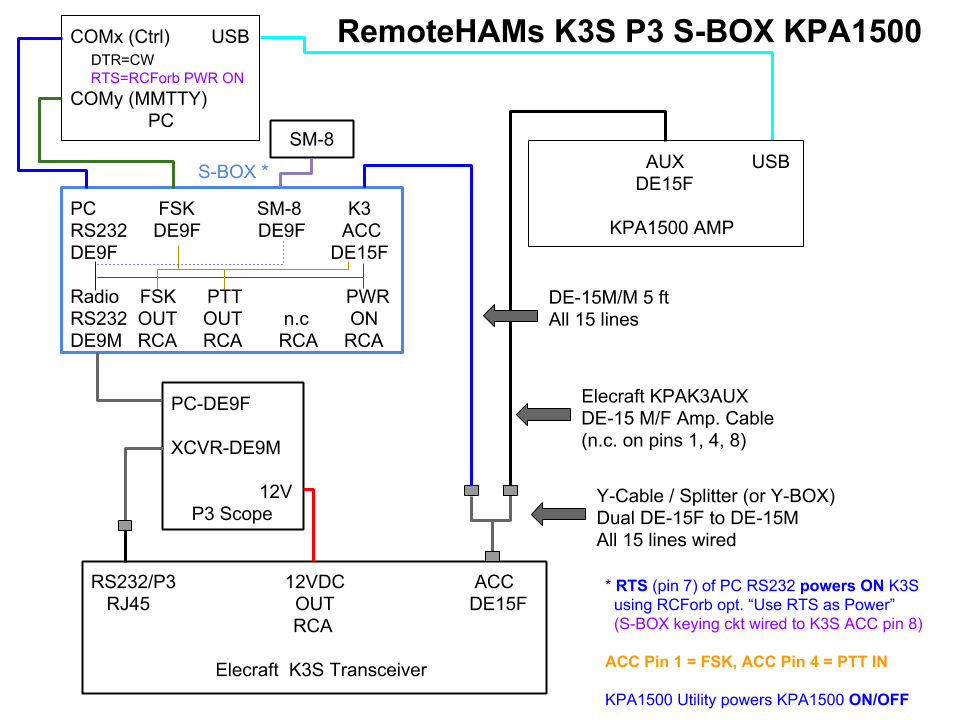
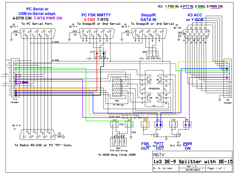
The S-BOX provides the keying circuit required to remotely power on a K3 or K3S from the serial port connection, using RCForb's Use RTS as Power option. Pulsing the RTS line of the serial port “high” momentarily grounds the PWR ON pin of the K3S ACC port (pin 8).
FSK RTTY and PTT keying from MMTTY is provided using the second serial port TXD and RTS lines. This port is wired to two more keying circuits. The output of the keying circuits is wired to the both the RCA connectors and to the K3 ACC port. A single 15-pin cable between the S-BOX and the K3 ACC port completes all connections. The third serial port is used to feed a ShackMaster SM-8 antenna controller, or a SteppIR controller, for automatic antenna switching or tuning. The antenna controller tracks the K3 frequency automatically.
Click to view PDF.
The RTS jumper is moved to the position shown by the purple arrow. The DTR line is passed straight through to the K3 for CW keying (set CONFIG:PTT-KEY to OFF-DTR).
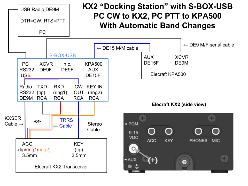
The S-BOX-USB makes it easy for a KX2 to be keyed by a computer over the same USB port being used for rig control. An Elecraft KPA500 is also connected and automatically follows band changes of the KX2. No custom or home-brew cables are required.
When you take your KX2 with you, just disconnect the cables from the side of the KX2 and leave everything else connected to the S-BOX.
A KXSER cable can be connected between the S-BOX Radio RS-232 and KX2 ACC serial port input.
-or-
A common RCA-to-3.5mm TRRS patch cable such as this one can be used for the KX2 ACC jack. A common RCA-to-3.5mm stereo patch cable such as this one can be used for the KX2 KEY jack.
The KPA500 XCVR connector is connected to the second serial port on the S-BOX, allowing the amp. to automatically monitor band changes by “listening in” on the serial port communications between the PC and the KX2. In the KPA500, set MENU:RADIO to SERIAL. If no PC is connected, in the KX2, set MENU:AUTOINF to ANT CTRL to provide the same info.
Click to view PDF.
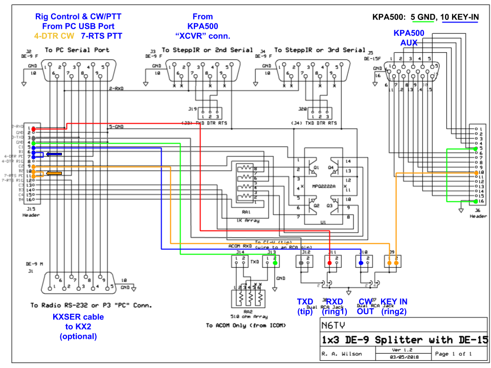
Two jumper wires (indicated by the red and gray lines in the schematic below) connect the RS-232 RXD and TXD lines of the PC serial port directly to the first two RCA connectors.
Inside the S-BOX, both shunt jumpers are moved to the positions shown by the blue and yellow arrows below, connecting DTR and RTS to the base (input) of two independent NPN keying transistors (labeled B1 and B2 on the header).
The CW output (C1) of the DTR keying circuit is connected to the third RCA connector, labeled CW OUT by a jumper wire (blue line). The PTT output (C2) of the RTS keying circuit (yellow line) is connected directly to the KPA500 KEY IN line (pin 10), closing the amplifier's relay as soon as PTT is asserted by the logging program. Connecting the KEY OUT (relay) line of the KX2 to the KEY IN RCA connector will hold the amplifier relay closed until the transceiver or logging program opens the line, whichever is later. This provides a safe and fast way to close the amplifier's relay in case the transceiver is late closing the RELAY line (insufficient TX DELAY).
Click to view PDF.
The S-BOX makes it easy for a KX3 to be keyed by a computer over the same serial port being used for rig control. An Elecraft KPA500 is also connected and automatically follows band changes of the KX3. No custom or home-brew cables are required.
When you take your KX3 with you, just disconnect the cables from the side of the KX3 and leave everything else connected to the S-BOX.
A KXSER cable can be connected between the S-BOX Radio RS-232 and KX3 ACC1 serial port input.
-or-
A common RCA-to-3.5mm stereo patch cable such as this one can be used for both the ACC1 (serial) and the KEY jack of the KX3.
A common RCA-to-2.5mm stereo patch cable such as this one can be used on the ACC2 (KEY OUT) jack.
The KPA500 XCVR connector is connected to the second serial port on the S-BOX, allowing the amp. to automatically monitor band changes by “listening in” on the serial port communications between the PC and the KX3. In the KPA500, set MENU:RADIO to SERIAL. If no PC is connected, in the KX3, set MENU:AUTOINF to ANT CTRL to provide the same info.
Click to view PDF.

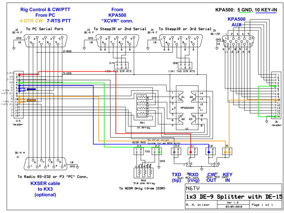
Two jumper wires (indicated by the red and gray lines in the schematic below) connect the RS-232 RXD and TXD lines of the PC serial port directly to the first two RCA connectors.
Inside the S-BOX, both shunt jumpers are moved to the positions shown by the blue and yellow arrows below, connecting DTR and RTS to the base (input) of two independent NPN keying transistors (labeled B1 and B2 on the header).
The CW output (C1) of the DTR keying circuit is connected to the third RCA connector, labeled CW OUT by a jumper wire (blue line). The PTT output (C2) of the RTS keying circuit (yellow line) is connected directly to the KPA500 KEY IN line (pin 10), closing the amplifier's relay as soon as PTT is asserted by the logging program. Connecting the KEY OUT (relay) line of the KX3 to the KEY IN RCA connector will hold the amplifier relay closed until the transceiver or logging program opens the line, whichever is later. This provides a safe and fast way to close the amplifier's relay in case the transceiver is late closing the RELAY line (insufficient TX DELAY).
Click to view PDF.
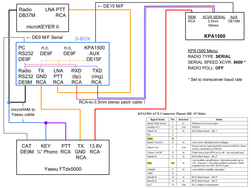
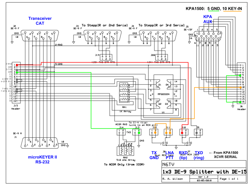
Instead of connecting the S-BOX to a PC serial port, it may instead be connected in series with a microHAM microKEYER II or similar to provide automatic frequency tracking from a transceiver to an Elecraft KPA1500 Amplifier. Since the FTdx5000 uses a DE-9M (male) COM connector, the serial cables are reversed from that shown in other diagrams (microKEYER on the Radio, connector, FTdx5000 on the PC connector).
The tip of the XCVR SERIAL connector on the KPA1500 (a 3.5mm stereo jack) must be connected to the RXD line of the PC serial port. The S-BOX makes it easy to make this connection using standard cables; no custom or home-brew cables are required. A common RCA-to-3.5mm stereo patch cable such as this one will work perfectly when connecting a KPA1500 to a transceiver via the S-BOX, as shown below.
The TX GND line from the FTdx5000 and the LNA PTT line from the microKEYER II are wired in parallel, allowing the KPA1500 QSK relay to be keyed in parallel with the CW. A straight 15-pin M/F cable completes the KEY IN connection to the KPA1500 AUX port.
The switched 13.8V output of the transceiver is connected to the REM jack on the KPA1500 to automatically switch the amplifier ON or OFF with the transceiver.
Click to view PDF.
With the red jumper wire connected to the RCA connector labeled RXD as shown below, the RXD line between the PC and the transceiver is “tapped”, so CAT traffic can be monitored by the KPA1500. The gray jumper wire on the TXD RCA connector is connected to allow the KPA1500 to poll the transceiver when the microKEYER II is powered OFF or disconnected. In this case RADIO POLL would have to be ON. Normally, while the microKEYER II is in control of the radio, it should be OFF.
Click to view PDF.
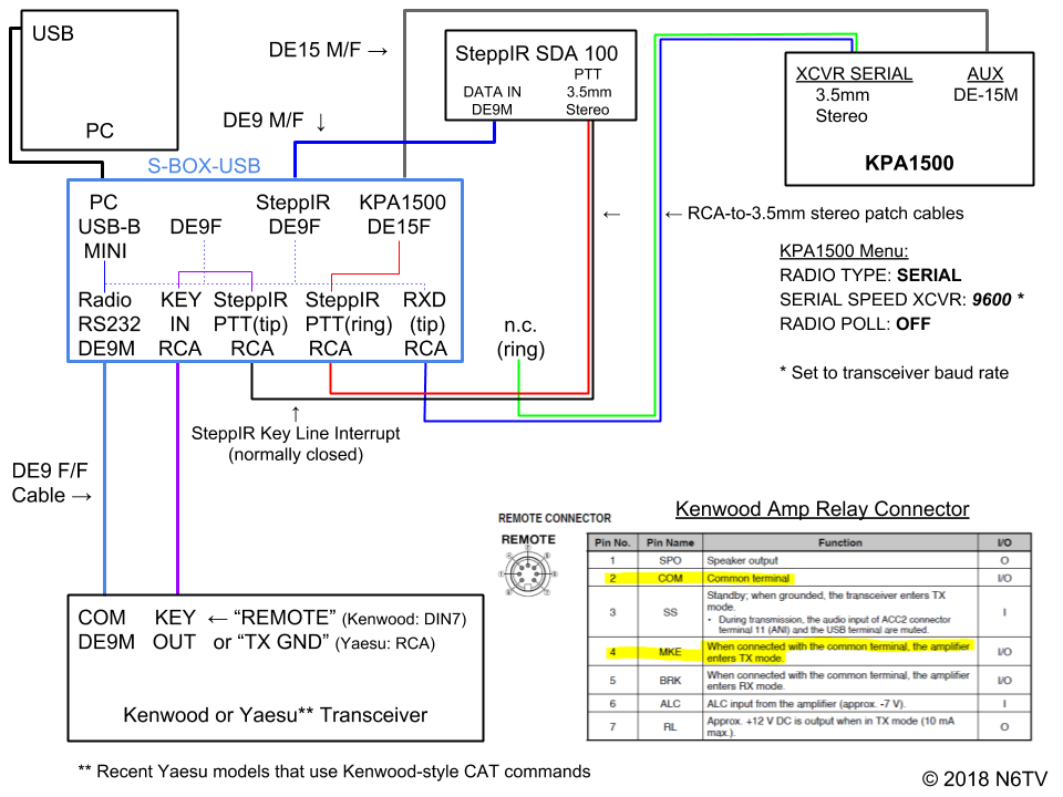
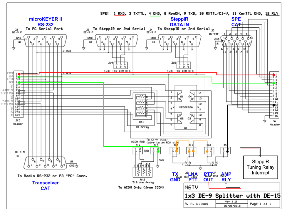
The Elecraft KPA1500 Amplifier can automatically change bands and retune when used with a modern Yaesu or Kenwood transceiver. The tip of the XCVR SERIAL connector on the KPA1500 (a 3.5mm stereo jack) must be connected to the RXD line of the PC serial port. The S-BOX and S-BOX-USB make it easy to make this connection using standard cables; no custom or home-brew cables are required. A common RCA-to-3.5mm stereo patch cable such as this one will work perfectly when connecting a KPA1500 to a transceiver via the S-BOX, as shown below.
Similarly, a SteppIR controller can simultaneously track the frequency of the transceiver, and automatically retune when necessary. Simply connect a serial cable between the SteppIR DATA IN connector and an available S-BOX serial port.
But, to prevent damage to a SteppIR antenna, it is very important to prevent high power from reaching the antenna until retuning is complete. The SteppIR Tuning Relay Interrupt option is designed to open the amplifier KEY IN line when necessary, an important safety feature. The S-BOX makes it easy to insert the SteppIR Tuning Relay Interrupt into the keying line between the transceiver and the amplifier.
A straight 15-pin M/F cable completes the KEY IN connection to the KPA1500 AUX port.
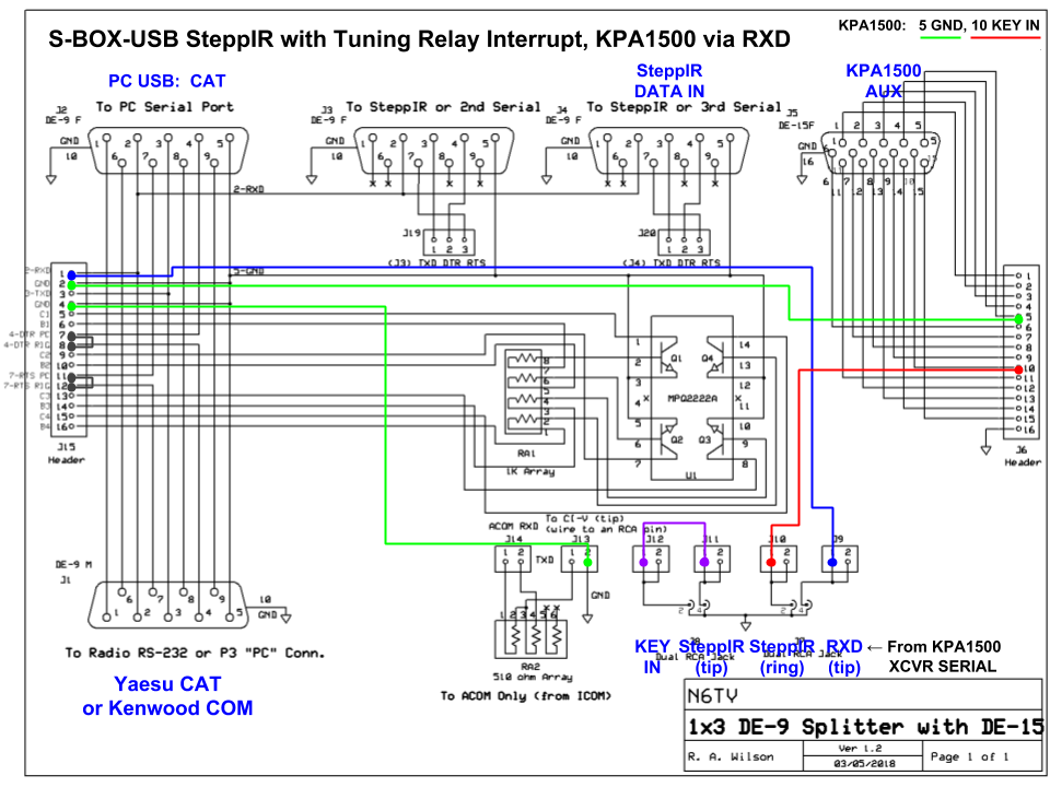
Click to view PDF.
With the blue jumper wire connected to the RCA connector labeled RXD as shown below, the RXD line between the PC and the transceiver is “tapped”, so CAT traffic can be monitored by both the SteppIR controller and the KPA1500. The SteppIR tuning relay interrupt, normally closed, completes the circuit between the transceiver KEY line and the KPA1500 KEY IN.
Click to view PDF.
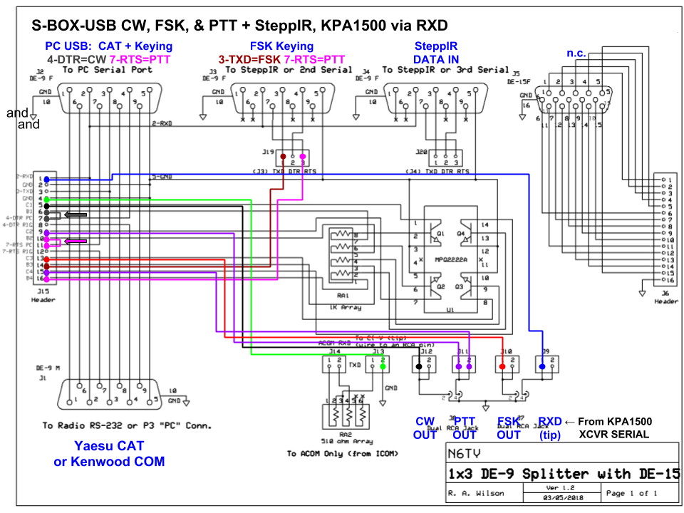
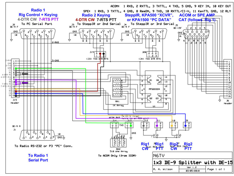
As in the previous example (above), we can use the S-BOX or S-BOX-USB to connect both an Elecraft KPA1500 Amplifier and a SteppIR antenna controller to a transceiver, with automatic frequency tracking. But this example uses all four keying circuits to provide computer-generated CW and FSK keying, using two independent serial ports. The CW PTT and FSK PTT lines are OR'd together inside the S-BOX, so both PTT inputs can be connected with a single cable to the transceiver.
The SteppIR Tuning Relay Interrupt option is connected as shown to open the amplifier KEY IN line when necessary, preventing high power from damaging the antenna.
Click to view PDF.
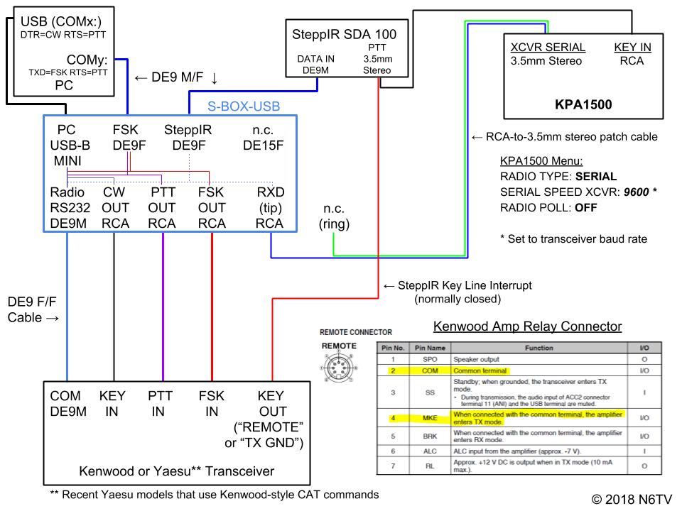
With the blue jumper wire connected to the RCA connector labeled RXD as shown below, the RXD line can be monitored by both the SteppIR and KPA1500.
With the shunt jumpers moved to the positions shown by the arrows, the DTR and RTS lines of the serial port used for CAT control are used to generate CW and PTT. The Red and pink jumper wires connect the TXD and RTS lines of the second serial port to two other keying circuits, providing FSK and PTT (for RTTY) . The two PTT outputs (magenta lines) are combined into a single RCA connector labeled PTT OUT.
Click to view PDF.
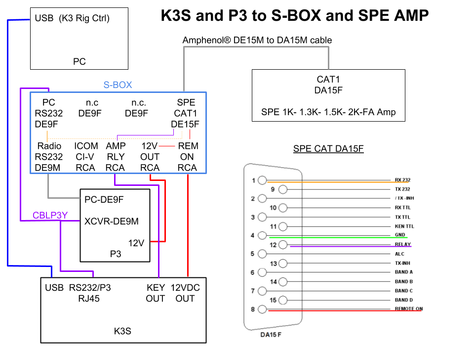
When connected to the S-BOX as shown below, SPE amplifiers can automatically track the frequency of a transceiver, and retune themselves automatically. The amplifier can also power on and off automatically whenever the transceiver powers on or off. This example shows an Elecraft K3S and P3 combination, but any supported transceiver will work the same way.
As indicated below with the magenta lines, the KEY OUT line from the K3S is connected to the RELAY line (pin 12) of the SPE CAT connector via the S-BOX. Only a single 15-pin cable is needed between the S-BOX and the SPE Amplifier.
Click to view PDF.
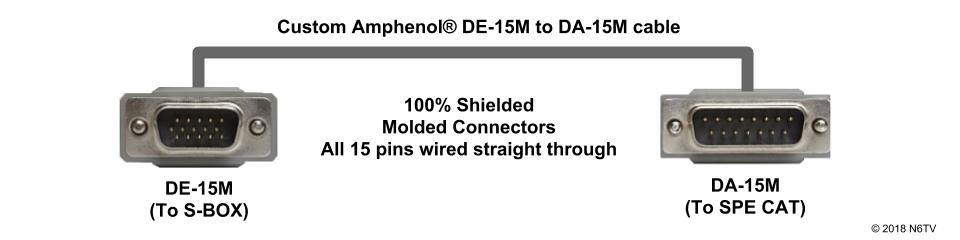
A custom Amphenol® DE-15M to DA-15M cable with molded connectors connects all 15 pins of the high-density (3-row) 15-pin connector on the S-BOX (DE-15F) to the standard (2-row) 15-pin CAT connector on the SPE amplifier (DA-15F), carrying both RS-232 signals and the RELAY line.
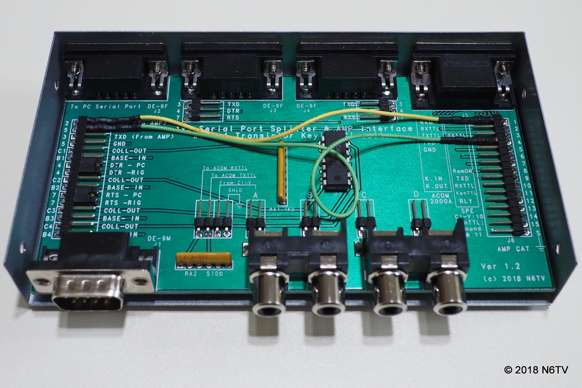
In photo below, a yellow jumper wire taps the RXD line (RS-232 pin 2) between the PC and the transceiver, connecting it in parallel with the RX 232 line (pin 1) of the 15-pin SPE CAT connector. Similarly, the green jumper wire connects the GND line (pin 5) to the SPE GND line (pin 4). Additional jumper wire connections are omitted for clarity (see matching schematic below).
This S-BOX schematic shows additional jumper wire connections (in red) that enable both the SPE amplifier and an Elecraft P3 to power ON automatically with the transceiver, using the 12 VDC output split two ways: (1) to a secondary 12 VDC output, and (2) to the REMOTE ON line (pin 8) of the SPE CAT connector.
Click to view PDF.
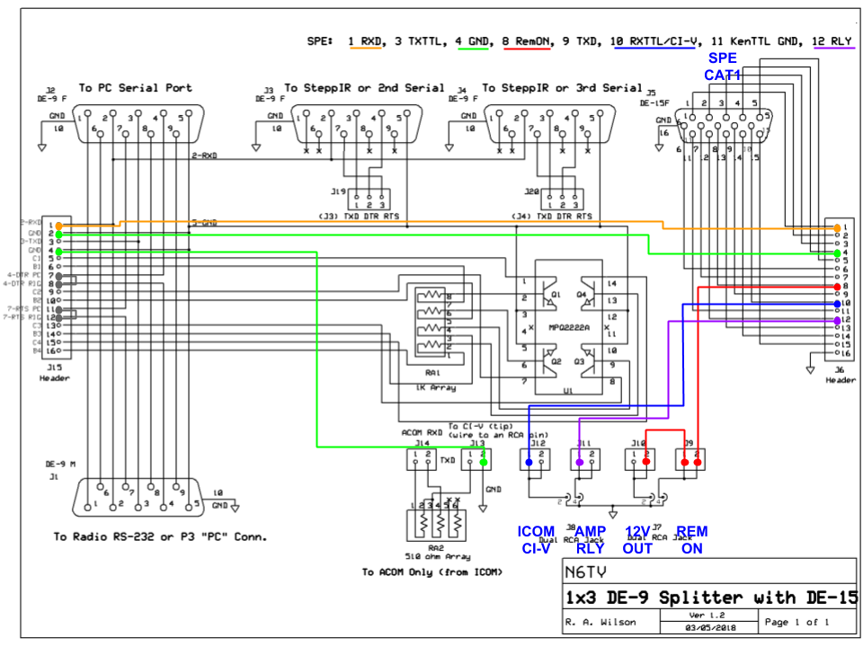
A microHAM microKEYER II or similar can be wired to a transceiver through the S-BOX, instead of direct to the radio's serial port, allowing both a SteppIR antenna controller and an SPE amplifier to track the transceiver's frequency automatically. The amplifier can also power on and off automatically whenever the transceiver powers on or off.
This example shows a Yaesu FTdx5000 being used, but any supported transceiver can work the same way.
Additionally, the LNA PTT output of the microKEYER is connected in parallel with the transceiver's TX GND line, so both are connected to the RELAY input (pin 12) of the SPE CAT connector through the S-BOX. Only a single 15-pin cable is needed between the S-BOX and the SPE Amplifier. This scheme provides more control over PTT lead time and could improve QSK performance by closing the amplifier's PTT line earlier than the FTdx5000 can do by itself.
Click to view PDF.
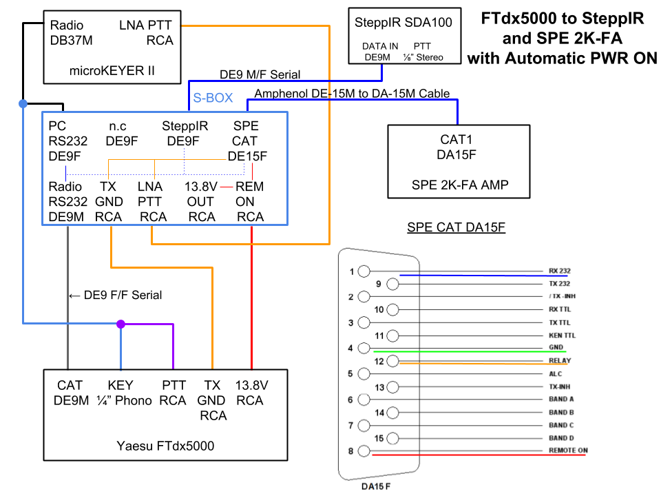
The schematic below shows the S-BOX internal jumper wires that connect the RS2-232 RXD and GND lines to pins 1 and 4 of the SPE CAT connector. The 13.8V output of the FTdx5000 is wired to the REMOTE ON line (pin 8) of the SPE Amplifier. 13.8V is also available to power other accessories via the adjacent RCA connector. The first two RCA connectors are both connected in parallel to the RELAY line (pin 12).
Click to view PDF.
The SteppIR SDA 100 antenna controller can include an optional Tuning Relay Interrupt board designed to open the RELAY line to the amplifier while the antenna is tuning, preventing high power from damaging the antenna. The S-BOX makes these connections very convenient using a common RCA-to-3.5mm stereo patch cable such as this one.
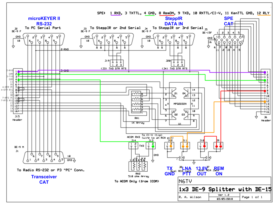
A microHAM microKEYER II or similar can be wired to a transceiver through the S-BOX, instead of direct to the radio's serial port, allowing both a SteppIR antenna controller and an SPE amplifier to track the transceiver's frequency automatically.
This example shows a Yaesu FTdx5000 being used, but any supported transceiver can work the same way.
Additionally, the LNA PTT output of the microKEYER is connected in parallel with the transceiver's TX GND line, and both are connected to the RELAY input (pin 12) of the SPE CAT connector through the Tuning Relay Interrupt. Only a single 15-pin cable is needed between the S-BOX and the SPE Amplifier. This scheme provides more control over PTT lead time and could improve QSK performance by closing the amplifier's PTT line earlier than the FTdx5000 can do by itself.
Click to view PDF.
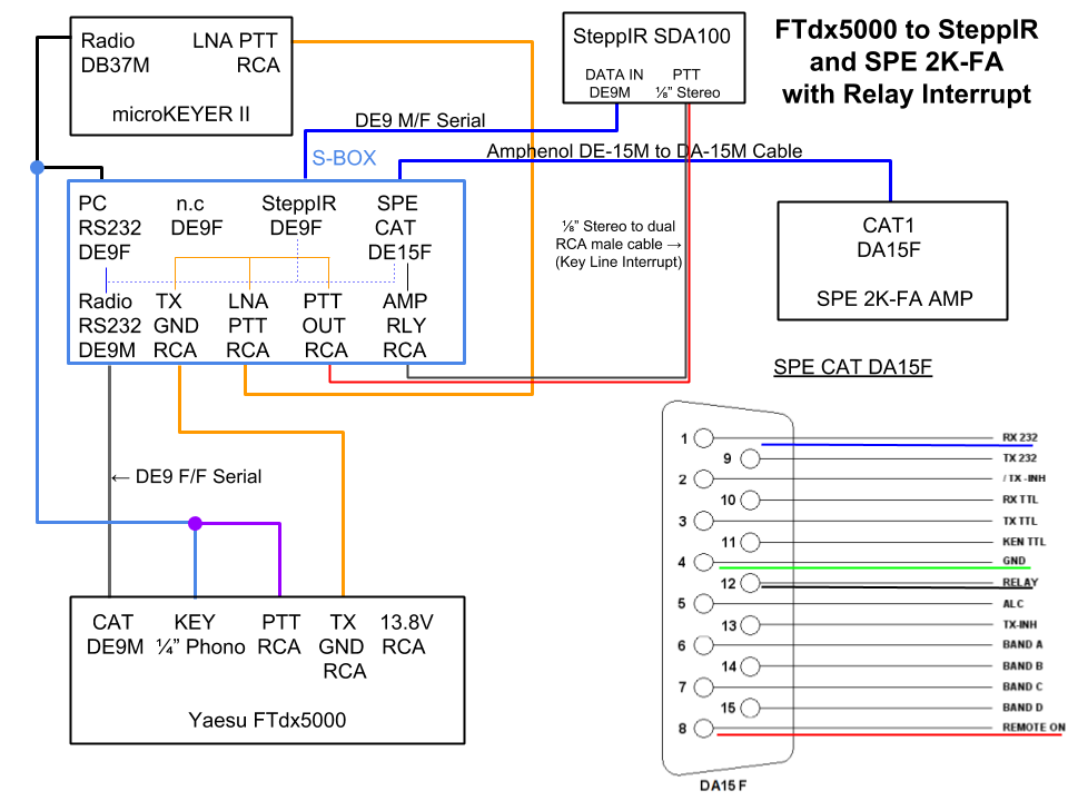
The schematic below shows the S-BOX internal jumper wires that connect the RS2-232 RXD and GND lines to pins 1 and 4 of the SPE CAT connector. The SteppIR Tuning Relay Interrupt is wired in series with the TX GND and LNA PTT inputs, allowing the SteppIR controller to open both lines to the amplifier whenever the antenna is retuning. This “normally closed” connection is wired to the RELAY line (pin 12) of the SPE CAT connector.
Click to view PDF.
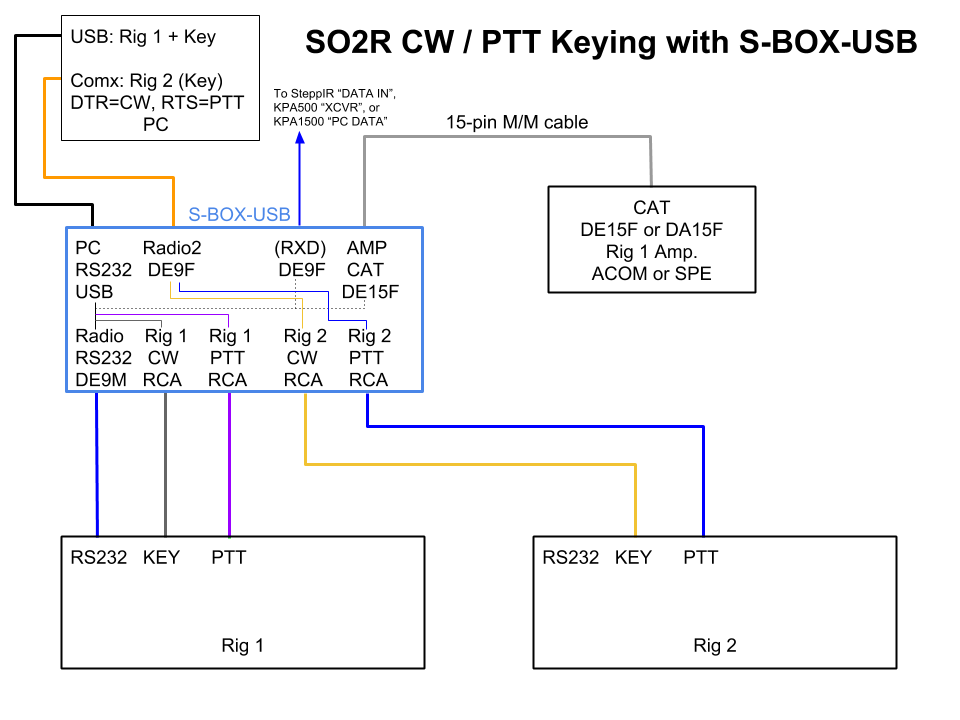
A logging program can use the four keying circuits inside the Serial Box to key CW and PTT on two different transceivers independently, using the DTR and RTS lines of two serial ports. The first serial port can simultaneously be used for rig control via CAT. CW sending works equally well with both real serial ports and FTDI USB-to-Serial adapters (virtual serial ports), including the FTDI adapter built-in to the S-BOX-USB as shown in this example.
The block diagram below shows the CW and PTT connections of the S-BOX, wired as described to two separate transceivers for SO2R CW.
Additionally, an SPE, ACOM or Elecraft amplifier, or a SteppIR Antenna Controller or equivalent, can be connected to the S-BOX at the same time, tracking Rig 1.
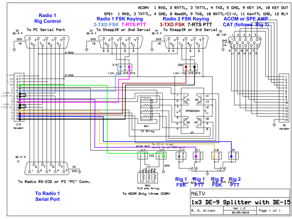
In the schematic below, the logging program keys CW on the DTR line (pin 4) of the rig control port, and keys PTT on the RTS line (pin 7). The control signals (CAT) are passed straight through to one transceiver (Radio 1). Similarly, the second serial port is used to send CW and PTT (only) to Radio 2.
Optionally, the 15-pin CAT port of an SPE or ACOM amplifier may be connected to the 15-pin connector on the S-BOX to monitor and track the frequency of Radio 1, enabling the amp. to retune or change bands, automatically following Radio 1 (RXD and GND jumpers not shown).
Furthermore, a SteppIR antenna controller, Elecraft KPA500 XCVR connector, or Elecraft KPA1500 PC DATA line can also track Radio 1. These would be connected to the 3rd serial port.
Click to view PDF.
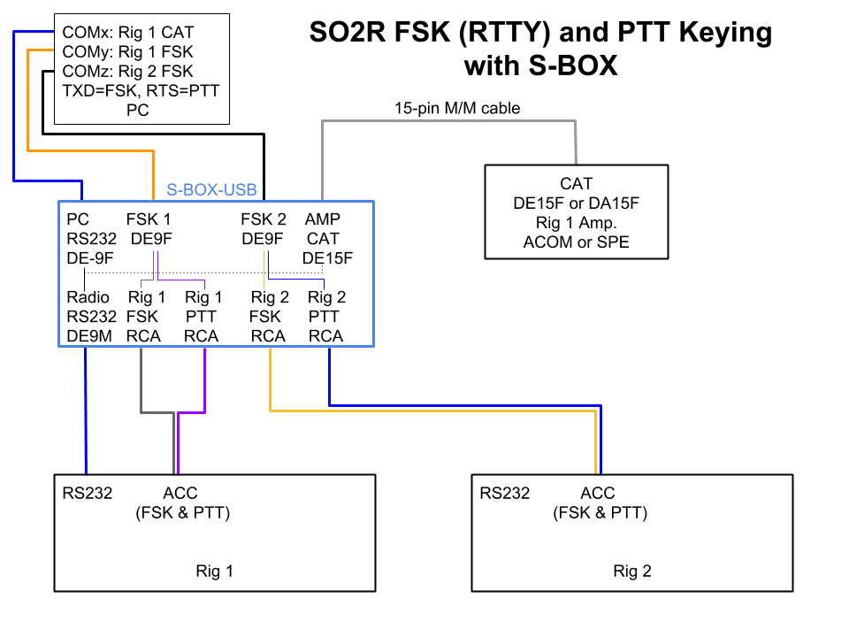
An program like MMTTY can use the four keying circuits inside the Serial Box to key the FSK and PTT lines of two different transceivers independently, using the TXD and RTS lines of two serial ports, by running a separate instance of MMTTY for each transceiver. The first serial port can be used for rig control via CAT. FSK keying can work well with both real serial ports and FTDI USB-to-Serial adapters (virtual serial ports), but one must use EXTFSK with MMTTY if using an FTDI virtual serial port.
Optionally, the 15-pin CAT port of an SPE or ACOM amplifier may be connected to the 15-pin connector on the S-BOX to monitor and track the frequency of Radio 1, enabling the amp. to retune or change bands, automatically following Radio 1.
The block diagram below shows the FSK and PTT connections of the S-BOX to two separate transceivers for SO2R RTTY:
In the schematic below, the first serial port is passing control signals (CAT) from the logging program straight through to Radio 1.
MMTTY keys FSK on the TXD line (pin 3) and PTT on the RTS line (pin 7) of the second serial port. Similarly, the third serial port is used to send FSK and PTT to Radio 2.
(The RXD and GND connections to the CAT connector are not shown.)
Click to view PDF.
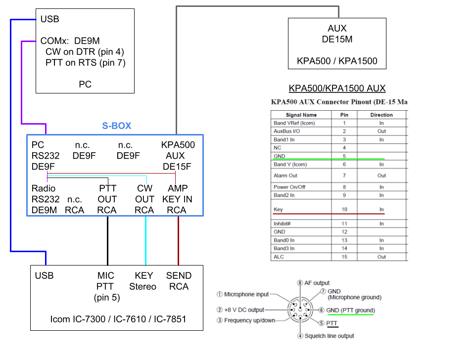
This design was inspired by N7YK, who wanted to key QSK CW and his amplifier at the same time while avoiding relay hot-switching caused by limited TX DELAY options in his transceiver.
The block diagram below shows the connections of the S-BOX to an Icom transceiver. Note how the SEND (keying relay) output of the transceiver is OR'd with the CW keying output via the RCA connector labeled AMP KEY IN. The CW keying will close the amplifier keying first. The SEND line will hold it closed until RF is no longer present, so there is no hot-switching at either the beginning or end of every CW element, assuming the rig provides some minimal delay between key closure and RF output, as most do. If they don't, semi break-in and PC control of PTT delay can resolve any hot-switching issues.
Click to view PDF. Scroll down to view schematic.
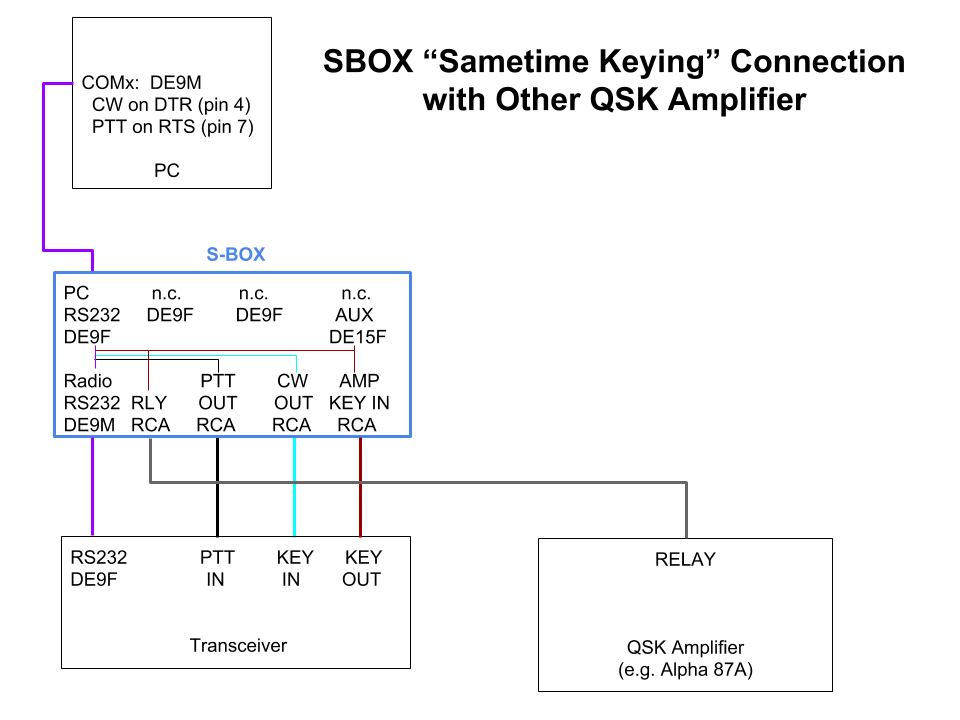
Even though the block diagram above shows an Icom transceiver and Elecraft amplifier, the same scheme can be used with any transceiver or amplifier, with the amplifier keyed through its 15-pin CAT/AUX port (if available), or by wiring the AMP KEY IN connector to the first RCA connector labeled RLY instead of to the AUX port header, then connecting an RCA cable to the amplifier's RELAY input instead of using the AUX cable for amplifier keying:
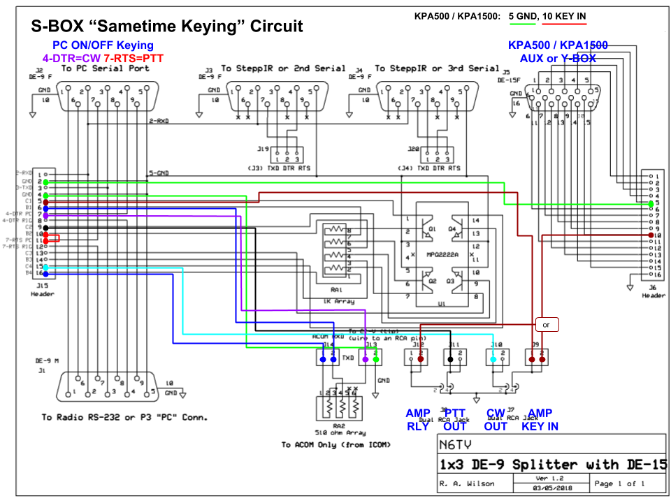
In the schematic below, the PC keys QSK CW on the serial DTR line (pin 4, magenta) which is split into two through a pair of 512 ohm resistors (the two dark blue lines). These are connected in parallel to the 1K resistors at the base of two keying transistors, Q1 and Q4, so both transistors are keyed simultaneously by the DTR pin. The output of Q1 (dark red line) is connected to the KEY IN line of the amplifier through its 15-pin accessory port (dark red line), and also to the fourth RCA connector labeled AMP KEY IN. The output of Q4 (cyan line) is connected to an RCA connector labeled CW OUT and is used to key the transceiver.
For semi break-in or phone, the RTS line (pin 7), is connected via shunt jumper (red) to the base of keying transistor Q2. The output of Q2 (black line) is connected to the second RCA connector labeled PTT OUT.
The use of the keying transistors prevents the closure of the SEND line from locking the rig key down.
Click to view PDF.
Connect up to four devices in parallel to a transceiver's serial port:
Serial port TXD, DTR, and RTS pins may also be connected to the inputs of four independent open-collector keying circuits to generate:
The outputs of the internal keying circuits may be wired to RCA connectors or to the 15-pin port for connection to an Elecraft K3/K3S AUX port or N6TV Y-BOX. A single 15-pin M/M cable then connects:
Replace a tangle of home-brew serial Y-cables with one box that provides solid shielded connections to all devices.
Connect any of the lines on the 15-pin CAT/AUX port of an SPE or ACOM Amplifier with new RCU to a simple RCA connector, including:
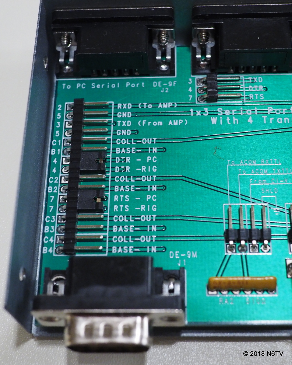
Commonly-used ACOM and SPE CAT port pins are clearly labeled on the internal 16-pin header, but all 15 pins plus the case ground may be connected as needed (click to enlarge):
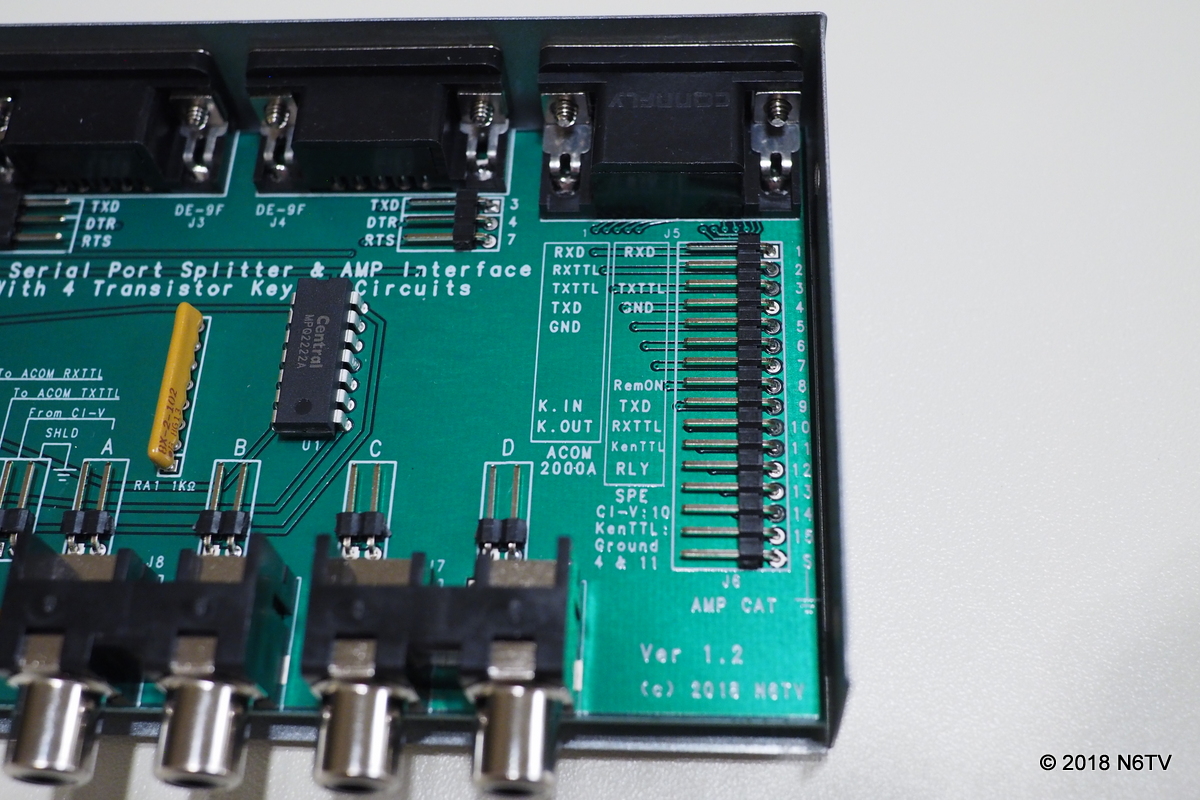
Standard 0.025" (0.635mm) jumper cables slide firmly over the pin headers and stay in place.
Click here to return to main page.