ke5c/m
[revised April 3, 2008]
-Use your browser's back button to
return to this page-
|
|
Click each thumbnail below
to enlarge. Use your browser's back button to return to this page. |
|
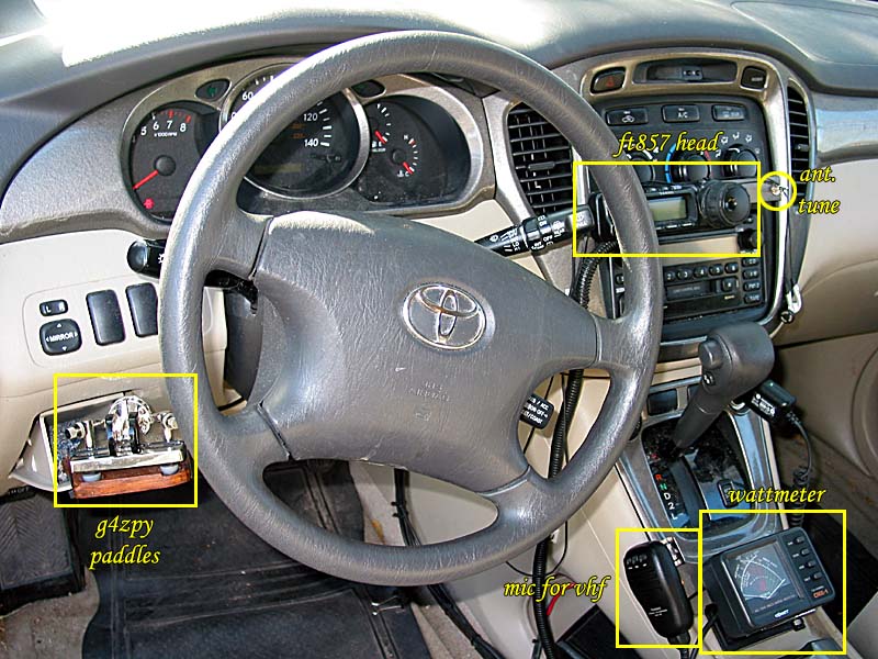 |
In the pictures below I will take you through the major features of my mobile shack. The paddles are mounted in a small storage compartment where I can rest my left hand on my left knee. The radio control head is mounted over the center console but I can still get to the controls above and below it. The microphone, used only for VHF, is mounted on the left side of the center console, and the wattmeter is mounted to the ash tray (non-smoker here). The SGC amplifier is just behind the center console in the rear seat area. |
 |
The FT-857 control head is mounted over the center console - see the next picture. The microphone mounting clip is screwed into the center console side wall below the trim to keep the screws invisible. See later pictures detailing paddle mounting in the storage compartment outlined by the yellow circle. |
 |
[April 2008] ID-800H added. |
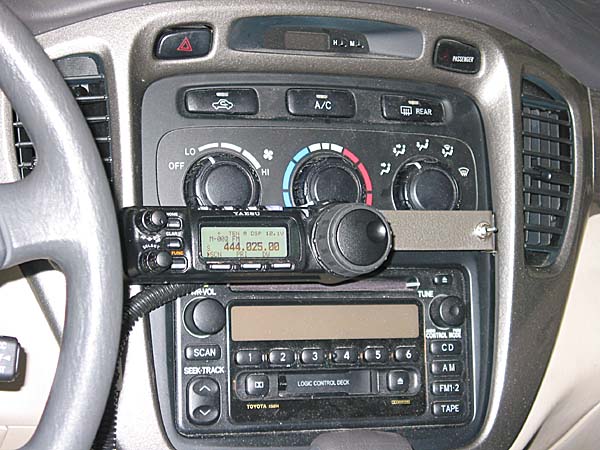 |
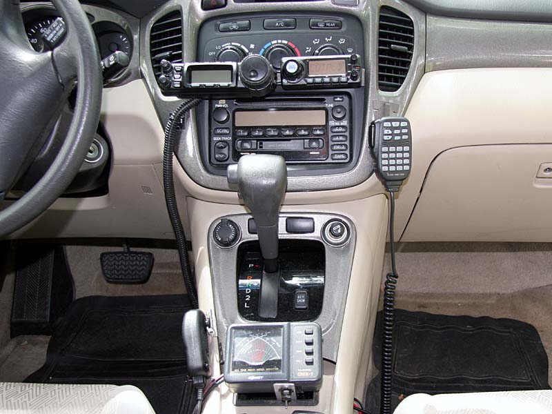
I made a custom bracket to hold the FT-857 control head over the center console controls. This location allows me to glance at the control head without completely removing my eyes from the road ahead. The ventilation controls are very slightly covered but still easily accessible. The CD slot for the AM/FM/CD/tape unit is just below the bottom of the bracket and also still accessible. The antenna tuning up/down switch is mounted on the far right side of the bracket. |
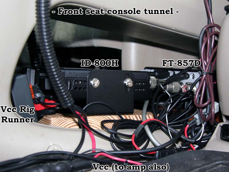 |
[April 2008 update] The FT-857, without control head, is mounted in the center console open storage space inbetween the driver and front passenger seats. The wood block has carpet on the bottom and on the side to absorb vibrations and avoid rattles. The FT-857D now shares this tunnel with the ID-800H. The front power cable to the amp is also visible. The Rig Runner distributes power from this cable to the rigs and will soon to a GPS. |
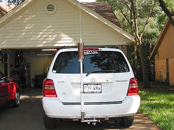 |
To maintain access to my rear cargo door, I considered a side mount, a rear mount with a fold over bracket, or a rear mount with a quick disconnect. A side mount would require welding to the trailer hitch, cause more wind noise, and provide more opportunities to ding the antenna when parking in many lots. Therefore, I chose a rear mount and narrowed my antenna choices to a Tarheel screwdriver and a Hi-Q tunable antenna. Since I plan to operate 40 meters primarily, the 4 inch diameter of the Hi-Q and the great quick disconnect system won. I had purchased a used bug-catcher but decided that I wanted to change bands without getting out of the vehicle to move the tuning tap. |
 |
I fashioned a lanyard from a bungee cord tied to a boat anchor rope which is waterproof and has a loop on one end. The bungee end hooks over my carrier rack, and I put a couple layers of heat shrink tubing over the hook to keep it from wearing the rack. The loop end simply slides over the antenna whip and rests at the whip base. I tried other arrangements with hard attachments to the Hi-Q at the top of the coil, but they did not survive the high RF environment well. |
 |
I started with a 102 inch whip that I already had. I couldn't tune 28 mhz, and I kept hitting low tree limbs. To know what to expect with different length whips, I measured the resonant frequency with miminum and maximum loading coil for no whip at all and three whips which I had. I have settled on a 72 inch whip which lets me tune 80 through 12 meters, but not 10. Oh well, a short whip would let me do that but would be less efficient, and I don't operate 10 meters much. |
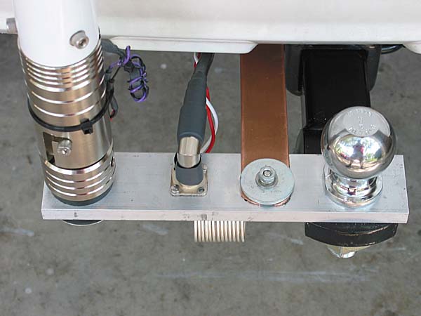 |
The Hi-Q MB-10 mounting bracket came drilled for a 1 inch shank trailer hitch. The ball holds the MB-10 to the hitch. Not trusting the trailer hitch assembly to make a good RF ground contact, I used a copper grounding strap with anti-oxident grease inbetween the copper and and the aluminum MB-10. The coax connects to a panel mount SO-239 connector, and the quick disconnect is visible on the far left. |
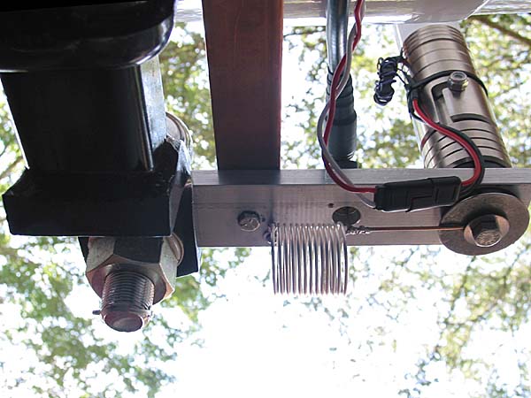 |
This is the MB-10 from below. |
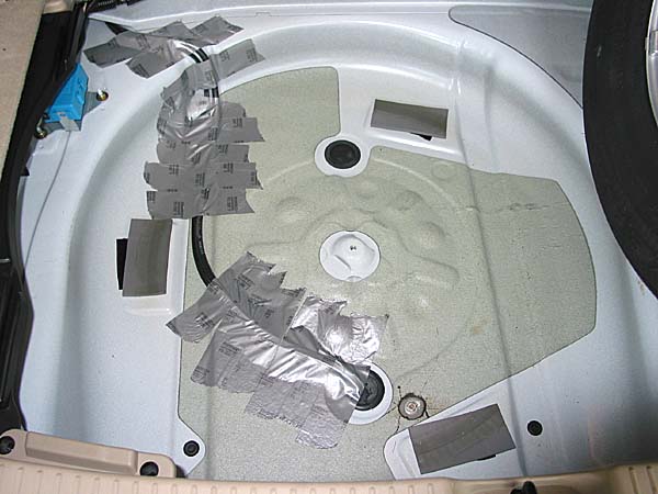 |
I was able to run the coax and the antenna tuning cable from the back seat area into the wheel well. There I used duct tape to hold it into place until the tire could. A drain plug was modified to serve as a grommet passing the cables to the underside of the car. Just to the right of the modified drain plug is the connecting bolt for the ground strap. I had to remove sound insulation in this area and grind the metal slightly to make a good contact from the inside. This may be unnecessary - see the next picture. |
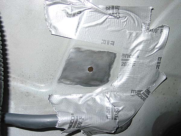 |
This is the bottom of the wheel well where the ground strap will mount. I used a wire wheel to get down to the bare metal removing the underside paint. The duct tape is masking as I prepared to spray undercoating on the completed assembly to protect against rust and corrosion. |
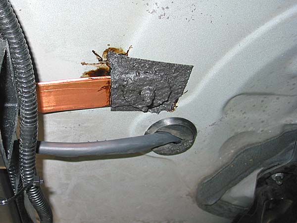 |
This is the completed ground strap attached and protected with undercoating spray in an aerosol can obtained from a local auto supply store. The masking tape has also been removed. The copper strap is actually 4 inches wide and used in commercial broadcasting for station grounds. I triple folded the strap, so the the actual width is now about 1.33 inches but three layers thick. The coax and up/down control cable are protected with heat shrink tubing. |
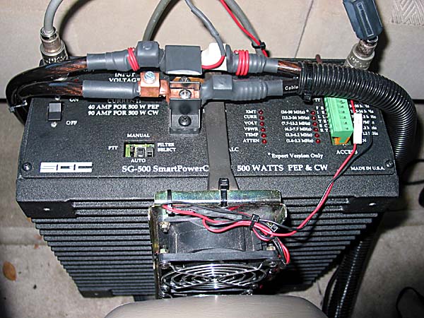 |
The SGC SG-500 amplifier sits in the rear seat foot area, and I can easily reach the off/on switch from the driver's seat. #4 wire from an audio store runs from a 150 amp fuse at the battery back to the amp. I tap this line for transceiver power, and I pick up grounds from the uni-body frame. I made an attachment point beneath the center console for the amplifier ground in the same fashion as the one for the ground strap above. The heat sink and three cooling fans face forward - the top fan is just visible. These are necessary for cw ragchewing with this amplifier. The fans used to be switched by the amplifier, but now I run them whenever the amplifier is on in order to keep things cooler from the start. |
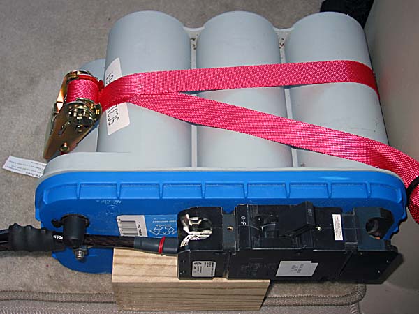 |
Later I added a second battery just behind the rear seat. The second set of power cables coming off the SG-500 in the picture above go back to this Optima marine battery which is sealed and can be mounted in any position. I was lucky to have a tie down hoop in a perfect location. I just ran a tie down strap around the battery and through the hoop which you cannot see but is just below the battery by the side of the cargo compartment. This battery has really reduced the amount my headlights dim when I transmit using the amp, and voltage at the amp has increased from 11.1 to 12.3 under full load. I bought a 150 amp DC breaker on eBay to use as an off/on switch and for protection for this second battery. It mounts directly to the marine connector. The wood block is to keep the breaker from rotating down since it is only attached to the terminal. |
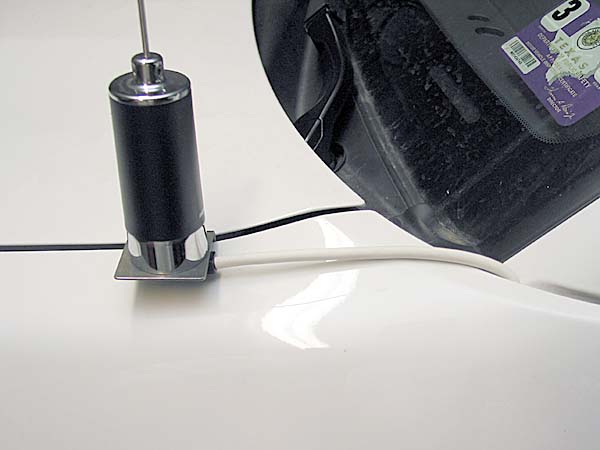 |
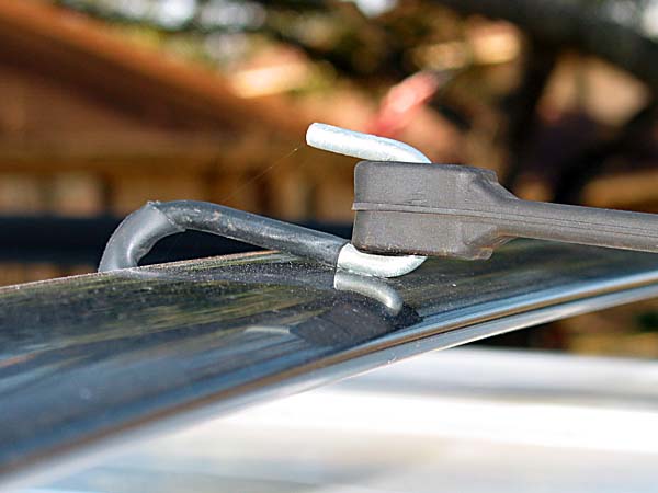
To avoid adding holes to my Toyota Highlander, I used a trunk lip mount on the hood side. Following Steve (NU5D's) suggestion, I used white heat shrink tubing to hide the otherwise black feedline. The coax snakes into the engine compartment where it joins and follows the #4 power wire through the firewall. |
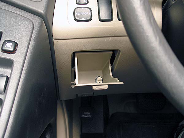 |
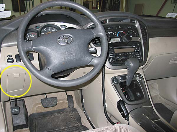
At first I used a leg key, but it was inconvenient to strap/unstrap everytime I wanted to operate, and it was hard to send clean code. One day while pondering my options, I noticed a little pull down storage compartment which covers the fuses. Since I use my left hand for paddles, I thought this might work. |
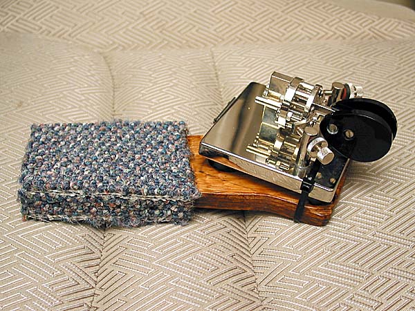 |
I fashioned a mounting plate from plywood to fit inside the holder. Outdoor carpet was glued on as a shock and vibration absorber. Finally the paddles were secured with a large tie wrap. |
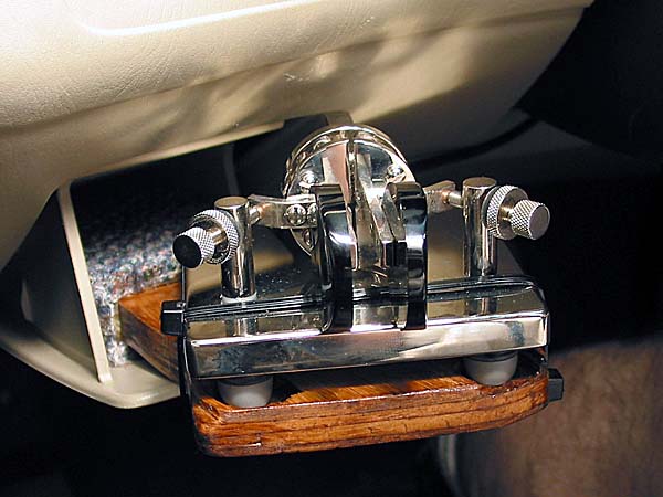 |
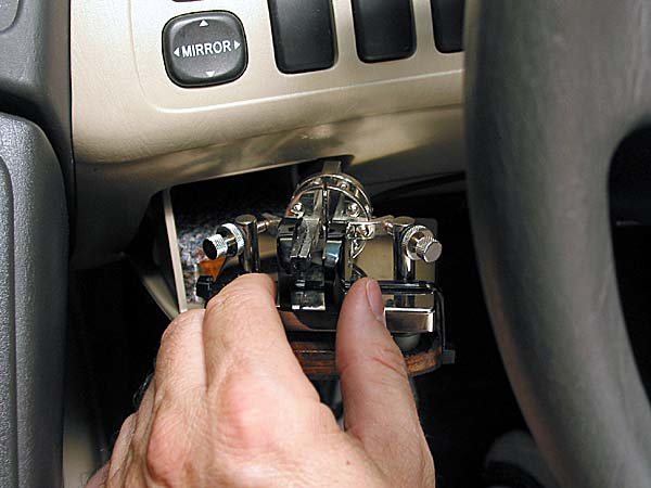
The mounting plate fits snuggly into the pull down storage compartment. The paddles are always available, and I find sending code much easier than when using a leg strap. |
 |
QRV! |
March/April 2008, revision 3
|
|
last revised:
August 26, 2012