
![]()
![]()
![]()
After using a 3-element KLM 40 meter beam for nearly 20 years at the previous QTH, I wanted something more reliable. There are just too many ways for a KLM 40 meter beam to become intermittent, and cause extreme interstation interference in an SO2R setup. I also was looking for ways to minimize cost - I simply couldn't lay out the money right now for a brand-new full size 40 meter beam.
In my aluminum scrap yard, I had all of the parts from the old KLM 40, plus parts from an old Hy-Gain 402BA that I recently picked up at a hamfest. I also picked up two 12' sections of stout 2" OD tubing at another hamfest. I really wanted to turn these into a full-size 2 element 40.
I spent hours struggling over Dave Leeson's "Physical Design of Yagi Antennas" and the element design spreadsheet that goes with it (downloadable from the ARRL web site). It was mighty tough coming up with a taper schedule for a full size 40 meter beam with the parts I had on hand. The biggest bottleneck was the reduction from 2" OD to 1 1/4" OD, without any intervening reductions. To accomplish the size reduction, I had aluminum reducers machined. They look like donuts (Nothing really new about this concept - I have seen it in many articles over the years). I used 2 reducers in each element-half. Since I couldn't find a local machine shop to do the work, I used eMachineShop.com. From my experience, I strongly recommend eMachineShop.com. They did exactly what I wanted, in the timeframe they promised, at a price competitive with out-of-town machine shops. Check them out !
The antenna ended up being a lot different from the original thoughts. First
of all, I
just couldn't see a way to make it 100% full size with the materials I had.
So, it turned out to be something like a modified Moxon, with 60 foot
elements on a 20 foot boom. The rest of the needed length is made up by
using wire to create a nearly rectangular antenna. It isn't a true Moxon
designed with his formulas - that would have shorter elements, a little less
gain, and a lot more F/B. I used Dacron rope as trusses to keep the tips
from bending in on each other due to the force of the Moxon tails pulling
inward.
I also went with a DE/reflector design rather than DE/director. I just
wasn't happy with a director - you either size it for the phone band, and
lose 1 dB gain on the CW band, or you size it for the CW band, and the
director is too long for the phone band and the pattern flips around as the
parasitic element looks like a reflector.
The matching is a bit unusual. For structural reasons, I didn't want to use a
split driven element. I used a tee match, without the capacitors at
the tee. I could have gone with a true tee match, with
capacitors at the tee, but with a 2 element beam, I didn't like the idea of
the capacitors being inaccessible without taking down the beam. At the
boom-to-mast plate is a matching network consisting of an
L-network and a 1:1 balun. I used a 100 ohm balanced feedline between the
matching network and the tee match. This 100 ohm feedline was fabricated with 2
parallel sections of Belden 9913.
I played with lots of different modeling software to make sure the design was
right - I was especially concerned about the tapered elements, which taper
down to 7/22 wire for the Moxon tails. It turned out that
MMANA (written by
JE3HHT) and TLW were the most useful, along with my old K6STI MN to confirm
what MMANA1 was telling me. A NEC-4 modeling program would have been
useful,
but they cost too much money. W4RNL's web site
was very useful, both for
Moxon info and modeling pitfalls. In addition, W6NL's has a paper on correcting
gamma and tee match models which was indispensable for understanding the
impedance
at the tee match, without the tee capacitors.
It went up in the air very smoothly. The only unforseen problem was the
Moxon tails and element trusses getting caught in the KT-34XA that is 30
feet down from the 40. Just not used to rectangular antennas and 60 foot
elements !
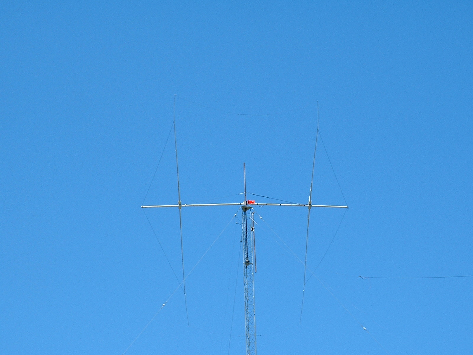
After using it for 9 months, I have nothing but good things to say about it. It performs far better than the old 3 element KLM did at the old QTH. It's typically 5-10 dB better than a dipole I had at the 70' level on the same tower. I'm sure that having it up 100', on the edge of a 300' dropoff towards EU has something to do with the way it plays ! So far, it has survived 45 MPH winds without a problem. Here's a picture of the antenna.
Since building this antenna, N7XM has made me aware of a
commercially manufactured 80 meter
antenna with a very similar design.
1. Be careful if you use MMANA. The dimensions are in meters, and the element size is radius, not diameter. In addition, it cannot import other antenna modeling files. Other than that, it's a fine piece of software.